Modifying a Deck
![]() Design Materials - Changing the Materials used in the Design
Design Materials - Changing the Materials used in the Design
| 1. | Select Plan View |
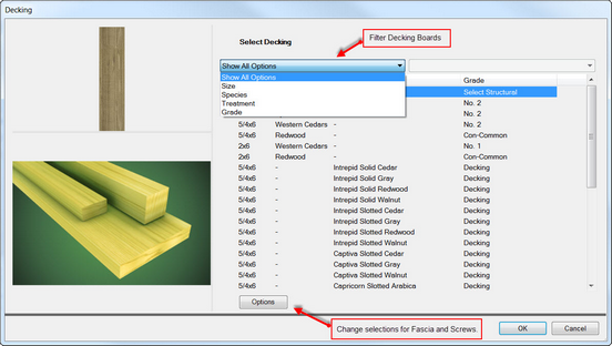
| 2. | To change Decking, Post, Joist and Beam Materials select Modify & Decks. Optional method, double the mouse click on the Deck surface to see Deck Properties dialog, select Materials tab. |
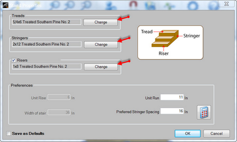
| 3. | To change Tread, Stringer and Riser Materials select Modify & Stairs. Optional method, double the mouse click on the Stairs to see Stair Properties dialog. |
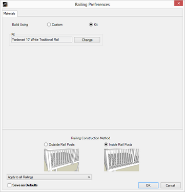
| 4. | To change Baluster, Rail Post and Railing Materials select Modify & Railings. Optional method, double the mouse click on the Stairs to see Stair Properties dialog, select Materials tab. |
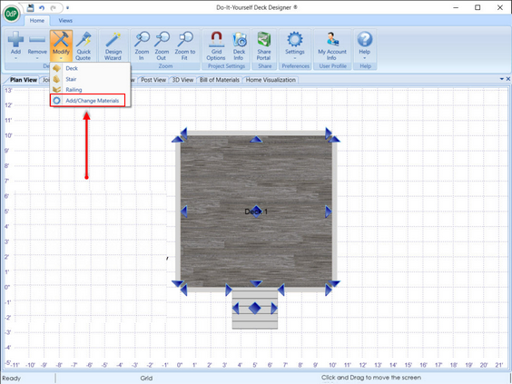
| 5. | To change all other materials such as hangars, screws, nails, etc., select Modify & Add/Change Materials. Optional method, double the mouse click on the Deck surface to see Deck Properties dialog, select Materials tab, select Edit button for General Project Materials. |
Note: By Selecting Add / Change Material an End-User has the ability to change certain materials such as fasteners, connectors, flashing, caps and concrete. The change can only be done to materials within the brand already selected
![]() Deck Properties - Change the Materials used in the Design and properties of the deck
Deck Properties - Change the Materials used in the Design and properties of the deck
| 1. | In Plan View, place the mouse pointer on an empty area of the deck surface and double-click the deck to open the Deck Properties dialog. The Deck Properties dialog can also be accessed by clicking Modify in the Home ribbon, and then selecting Deck from the menu. If multiple decks exist, you will be prompted to choose a deck to edit. |
| 2. | Use the tabs to choose the preferred materials, construction method, and other deck options. |
| 3. | Click the OK button to return to the design. |
This dialog contains the following tabs:
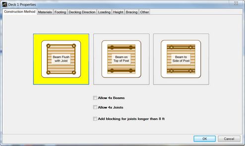
![]() Construction Method
Construction Method
From this tab you can select from among several construction styles. You can also choose to add blocking when the lengths of joists exceed 8 feet.
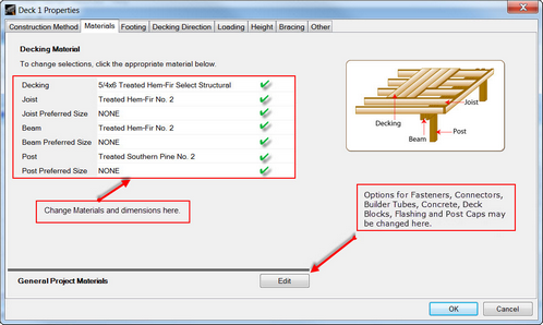
![]() Materials
Materials
From this tab you can change the materials used for decking, joists, beams, posts, and fasteners.
To change materials:
| 1. | Click a material link on the left. |
| 2. | Select a material from the list. |
| 3. | Click OK. |
Note: If you have no size preferences and want the system to build the deck using the best sizes for joists, beams and posts, choose NONE for Preferred Sizes.
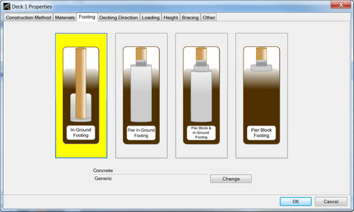
![]() Footing
Footing
Select a post footing style from this tab.
Note: By selecting Pier In-Ground Footing or Pier Block In-Ground Footing will cause Sono-tubes (Builder tubes) to automatically also be included (Bid) on the Bill of Material.
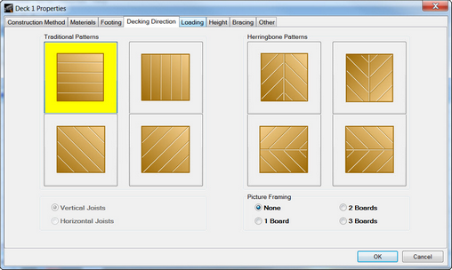
![]() Decking Direction
Decking Direction
Select a traditional pattern (horizontal, diagonal, or vertical) or herringbone pattern from this tab.
Note: When selecting diagonal decking, you must choose either Horizontal Joists or Vertical Joists. The herringbone option supports adding decorative borders around the deck (Picture Framing).
Note: When selecting picture framing, the color of the lumber used in the picture framing is not selectable in the application.
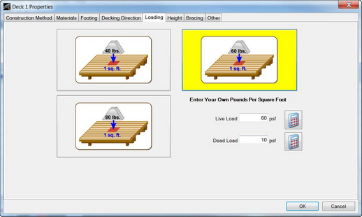
![]() Loading
Loading
Enter dead load and live load in pounds per square foot (PSF).
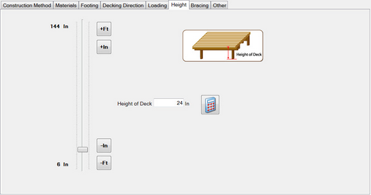
![]() Height
Height
Set the deck height using the sliding bar or by typing the measurements.
Note: If you set the deck 32" high or higher, the system prompts you to add railings for safety when you close the Deck Properties dialog.
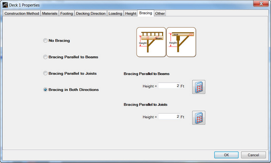
![]() Bracing
Bracing
Click the option button beside the preferred bracing method. The default height is 2' for all options and you can enter your own value here.
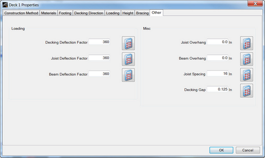
![]() Other
Other
This tab controls preferences for the following. These settings also appear in the project specs.
| • | Loading |
Deflection Factors: Displacement of a structural member (decking, beams, posts) under load. Default = 360
A deflection factor of 240 means that, under load, a structural member (beam, joist, decking board) will deflect (move) no more than 1/240th of its length. Take for example a 10-foot-long beam. 1/240th of 10 feet is ½". When fully loaded (with the dead load and live load used), the center flexes down. If the vertical displacement at the center is ½" or less, then the deflection is permissible with a deflection factor of 240. A higher deflection factor means that less deflection is allowed.
Deflection is what makes decks (or other structures) feel wobbly or feel weak. It is possible to make a structure that is in fact strong enough to hold up under a load, but is still wobbly. Not only do people not like wobbly structures, the continual slight movement may eventually weaken the structure; in wooden structures the connectors or wood-connector joints are the typical points of failure in this case. By ensuring that the structural members meet the deflection test, this problem is avoided. In most cases, the design parameter that actually limits how long a beam or joist can be (before it has to be replaced with a larger one) is the deflection factor.
| • | Miscellaneous: |
| • | Joist Overhang: Default = 12 decimal inches |
| • | Beam Overhang: Default = 6 decimal inches |
| • | Joist Spacing: Default = 16 decimal inches |
| • | Decking Gap: Default = 0.25 decimal inches |
Note: To create new default settings for decks, select the Save as Defaults check-box.
Changing the Size of a Deck
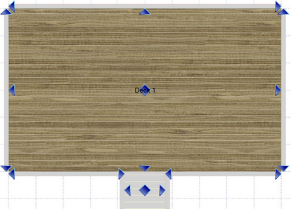
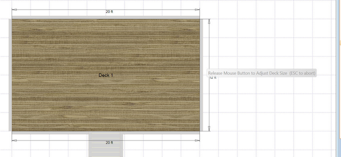
Change the length of a deck side by dragging a grip point (represented by ![]() ) to a new location on the design grid. Place the mouse pointer over the grip point and hold the left mouse button to move the deck to a different location on the grid.
) to a new location on the design grid. Place the mouse pointer over the grip point and hold the left mouse button to move the deck to a different location on the grid.
Note: As you drag an edge, measurements along dimension lines display new values.
Moving a Deck
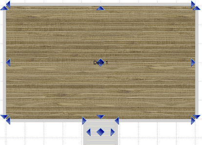
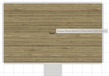
To move a deck on the grid, drag it by the grip point located in the center of the deck, (represented by ![]() ). Place the mouse pointer over the grip point and hold the left mouse button to move the deck to a different location on the grid.
). Place the mouse pointer over the grip point and hold the left mouse button to move the deck to a different location on the grid.
Note: A deck attached to a wall cannot be moved.
Removing a Deck
| 1. | Click the Remove button in the Home ribbon. |
| 2. | From the Remove menu, select Deck. |
| 3. | Click the deck to be removed. |
Note: Removing a deck removes all associated structures, such as stairs, railings, etc.
